Direct answer
Size a metal expansion joint slot width or oversized panel clearance hole to exceed the maximum anticipated thermal movement from the panel's fixed restraint point plus fabrication and installation tolerances. Linear expansion in inches is ∆L = 12(∆T)(L)(E), where ∆T is the surface temperature differential (°F), L is panel length (ft), and E is the metal's coefficient of linear expansion (0.0000065 /°F for steel and 0.0000128 /°F for aluminum). For riveted rainscreen panels such as ALUCOBOND (2.4 mm/m/100 K), center an Ø 5 mm blind rivet inside an Ø 7.0 mm or Ø 8.5 mm panel clearance hole with a 0.3 mm axial stand-off gap under the rivet head, and anchor each panel and support rail at one dedicated fixed point so thermal growth moves freely toward the slotted expansion connections.
Key takeaways
- Calculate unconstrained panel length change as ∆L = 12(∆T)(L)(E) in inches, or 2.4 mm per meter per 100 K for aluminum and ALUCOBOND facades.
- Center each sliding fastener inside an oversized panel hole (such as Ø 7.0 mm or Ø 8.5 mm for an Ø 5 mm ALUCOBOND rivet) with a 0.3 mm axial clearance under the fastener head.
- When the shaft of the rivet fits closely to the edge of the panel hole at maximum thermal movement, the rivet head must cover over 1 mm of the area surrounding the hole.
- Rainscreen panels require a fixed point to avoid slippage because if all holes in the panel are oversized and the fastener is held off, the panel will slip; fixed point sleeves can also create a fixed point inside an oversized hole.
- A stand-off nose piece should be used with centering tools when installing facade rivets to hold the rivet off the face of the panel usually by a fraction of a millimetre so the panel is clamped but not locked.
Every architectural metal wall connection must accommodate the thermal movement for which it was designed, using floating clips, slotted rail holes, and oversized panel bores so temperature swings do not lock the cladding into skin compression and oil canning. Sizing the slot width or hole clearance starts with calculating the panel’s free thermal growth from its fixed anchor point across the seasonal surface temperature range, then centering the fastener with controlled axial stand-off so the sheet can slide without binding.
For related wall assembly criteria across our design and specification hub and specification overview, review the metal wall coverings guide alongside metal wall panel installation and oil canning in metal panels.
Linear thermal expansion equations and metal coefficients
Sentrigard defines change in sheet length (in inches) as ∆L = 12(∆T)(L)(E), where ∆T is temperature change in degrees F, L is total sheet length in feet, and E is the coefficient of linear expansion. Metal Sales gives Δ Length (in inches) = Length (in inches) * Δ Temperature (in °F) * ε, with ε = 0.0000065 / °F for steel and 0.0000128 / °F for aluminum, yielding 0.78” expansion on a 100’ long steel panel over a 100°F change (and 1.56” for aluminum). Petersen Aluminum (PAC-CLAD) states that aluminum expands and contracts almost twice as much as steel: for every 100°F temperature swing, a 30-foot aluminum panel could move about 7/16 of an inch, while a similar steel panel might move only about one quarter inch.
Sentrigard lists a coefficient of linear expansion E of 0.0000065 for Galvanized or Galvalume Steel. Sentrigard lists a coefficient of linear expansion of 0.0000128 for Aluminum. Sentrigard lists a coefficient of linear expansion of 0.0000099 for Stainless Steel. Sentrigard lists a coefficient of linear expansion of 0.0000093 for Copper. Sentrigard lists coefficients of linear expansion of 0.0000165 for Zinc and 0.0000370 for polycarbonate.
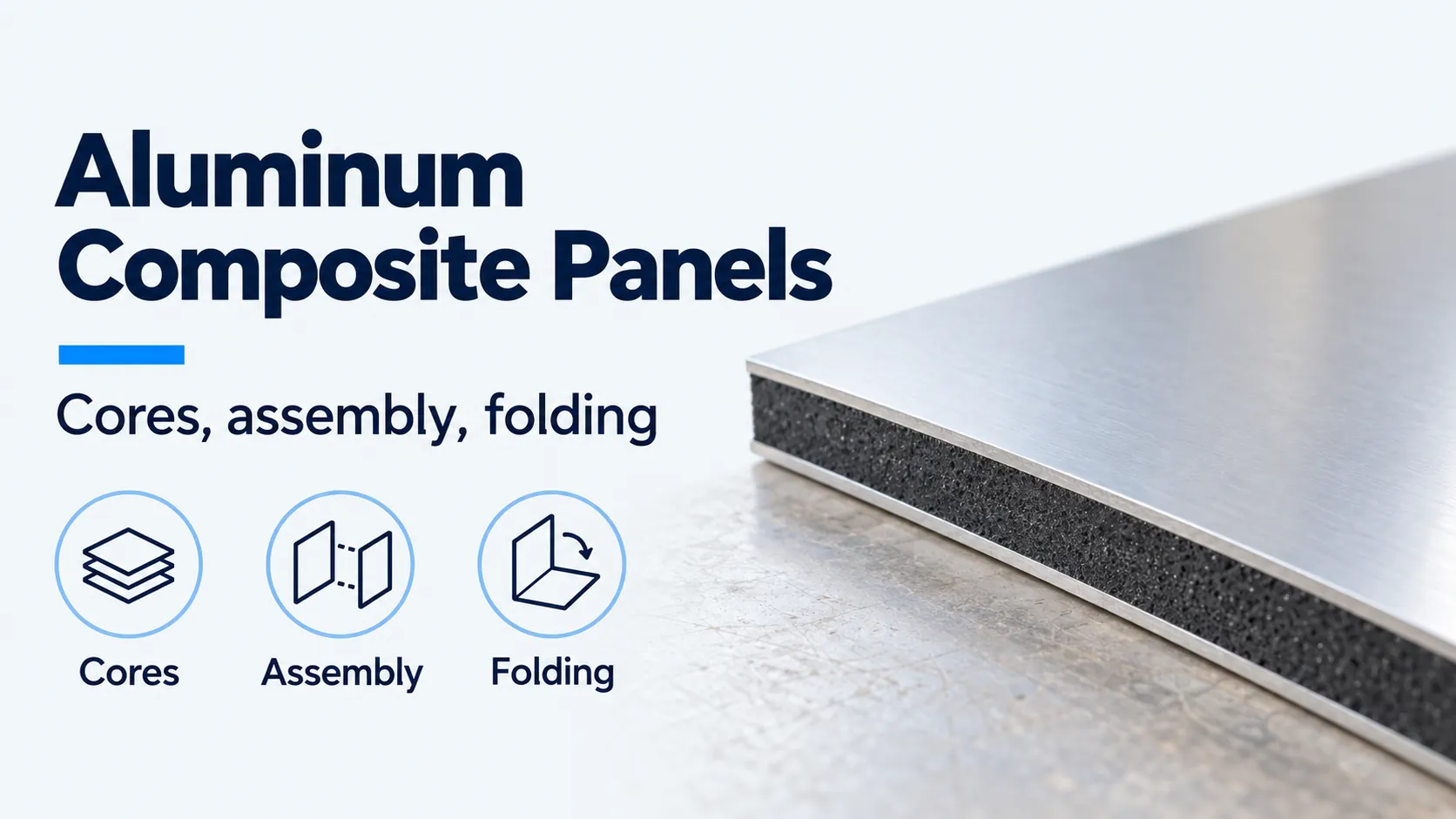
ALUCOBOND has a linear expansion coefficient of 2.4 mm/m/100 K, requires centric drilling of holes in the panel and substructure using drilling jigs, and requires a 0.3 mm distance between the panel and rivet head using rivet attachment jigs. At a 1 m panel and 50 K temperature difference, linear thermal expansion coefficients and movements are 24 x 10 -6 (1.2 mm) for ALUCOBOND and Aluminium, 12 x 10 -6 (0.6 mm) for Steel and Concrete, 5 x 10 -6 (0.25 mm) for Wood, and ~ 70 x 10 -6 (3.5 mm) for PVC. RHEINZINK architectural titanium zinc has an expansion coefficient of 2.2 mm/m x 100 K in the rolling direction and 1.7 mm/m x 100 K transverse to the rolling direction. Deer Park Roofing states that the coefficient of expansion is constant across all metal thicknesses, so 24-gauge galvanized steel has the same coefficient as 26-gauge galvanized steel, and 16-ounce copper has the same coefficient as 20-ounce copper.
Published linear thermal expansion coefficients across architectural cladding materials and substrates.
| Material or panel system | Published expansion coefficient and reference movement |
|---|---|
| Galvanized or Galvalume steel | Sentrigard lists a coefficient of linear expansion E of 0.0000065 for Galvanized or Galvalume Steel. |
| Aluminum | Sentrigard lists a coefficient of linear expansion of 0.0000128 for Aluminum. |
| Stainless steel | Sentrigard lists a coefficient of linear expansion of 0.0000099 for Stainless Steel. |
| Copper | Sentrigard lists a coefficient of linear expansion of 0.0000093 for Copper. |
| Zinc and polycarbonate | Sentrigard lists coefficients of linear expansion of 0.0000165 for Zinc and 0.0000370 for polycarbonate. |
| RHEINZINK titanium zinc | RHEINZINK architectural titanium zinc has an expansion coefficient of 2.2 mm/m x 100 K in the rolling direction and 1.7 mm/m x 100 K transverse to the rolling direction. |
| Metric comparison materials | At a 1 m panel and 50 K temperature difference, linear thermal expansion coefficients and movements are 24 x 10 -6 (1.2 mm) for ALUCOBOND and Aluminium, 12 x 10 -6 (0.6 mm) for Steel and Concrete, 5 x 10 -6 (0.25 mm) for Wood, and ~ 70 x 10 -6 (3.5 mm) for PVC. |
To compare alloy behavior across facade profiles, see aluminum vs steel wall panels, aluminum composite panels, and zinc wall cladding in the materials hub and comparisons hub.
Tabulated panel length changes and surface temperature differentials
In Sentrigard Table 1 for Galvanized and Galvalume Steel panels, a 10 ft panel length changes length (in inches) across the seven temperature differential columns (ΔT = 60°F, 80°F, 100°F, 120°F, 140°F, 160°F, and 180°F) by 0.047, 0.062, 0.078, 0.094, 0.109, 0.125, and 0.140 in. A 20 ft steel panel length changes length across the same seven ΔT columns by 0.094, 0.125, 0.156, 0.187, 0.218, 0.250, and 0.281 in. A 30 ft steel panel length changes length by 0.140, 0.187, 0.234, 0.281, 0.328, 0.374, and 0.421 in., while a 40 ft steel panel length changes length by 0.187, 0.250, 0.312, 0.374, 0.437, 0.499, and 0.562 in.
In Sentrigard Table 2 for Aluminum panels across the same seven temperature differentials (60°F to 180°F in 20°F increments), a 10 ft panel length changes length by 0.092, 0.123, 0.154, 0.184, 0.215, 0.246, and 0.276 in., and a 20 ft panel length changes length by 0.184, 0.246, 0.307, 0.369, 0.430, 0.492, and 0.553 in. A 30 ft aluminum panel length changes length by 0.276, 0.369, 0.461, 0.553, 0.645, 0.737, and 0.829 in., while a 40 ft aluminum panel length changes length by 0.369, 0.492, 0.614, 0.737, 0.860, 0.983, and 1.106 in. In Sentrigard Table 3 for Stainless Steel panels, a 10 ft panel length changes length across the seven ΔT columns by 0.071, 0.095, 0.119, 0.143, 0.166, 0.190, and 0.214 in., and a 30 ft panel length changes length by 0.214, 0.285, 0.356, 0.428, 0.499, 0.570, and 0.642 in. In Sentrigard Table 4 for Copper panels, a 10 ft panel length changes length across the seven ΔT columns by 0.067, 0.089, 0.112, 0.134, 0.156, 0.179, and 0.201 in., and a 30 ft panel length changes length by 0.201, 0.268, 0.335, 0.402, 0.469, 0.536, and 0.603 in.
Published panel length changes (in inches) from Sentrigard Technical Bulletin tables across ΔT = 60°F, 80°F, 100°F, 120°F, 140°F, 160°F, and 180°F.
| Metal family | Published length changes (in.) across ΔT = 60°F to 180°F (in 20°F steps) |
|---|---|
| Galvanized and Galvalume steel (10 ft run) | In Sentrigard Table 1 for Galvanized and Galvalume Steel panels, a 10 ft panel length changes length (in inches) across the seven temperature differential columns (60°F to 180°F) by 0.047, 0.062, 0.078, 0.094, 0.109, 0.125, and 0.140 in. |
| Galvanized and Galvalume steel (20 ft run) | In Sentrigard Table 1 for Galvanized and Galvalume Steel panels, a 20 ft panel length changes length (in inches) across the seven temperature differential columns (60°F to 180°F) by 0.094, 0.125, 0.156, 0.187, 0.218, 0.250, and 0.281 in. |
| Galvanized and Galvalume steel (30 ft and 40 ft runs) | In Sentrigard Table 1 for Galvanized and Galvalume Steel panels, a 30 ft panel length changes length (in inches) across the seven temperature differential columns by 0.140, 0.187, 0.234, 0.281, 0.328, 0.374, and 0.421 in., while a 40 ft panel length changes length by 0.187, 0.250, 0.312, 0.374, 0.437, 0.499, and 0.562 in. |
| Aluminum (10 ft and 20 ft runs) | In Sentrigard Table 2 for Aluminum panels, a 10 ft panel length changes length (in inches) across the seven temperature differential columns (60°F to 180°F) by 0.092, 0.123, 0.154, 0.184, 0.215, 0.246, and 0.276 in., and a 20 ft panel length changes length by 0.184, 0.246, 0.307, 0.369, 0.430, 0.492, and 0.553 in. |
| Aluminum (30 ft and 40 ft runs) | In Sentrigard Table 2 for Aluminum panels, a 30 ft panel length changes length (in inches) across the seven temperature differential columns by 0.276, 0.369, 0.461, 0.553, 0.645, 0.737, and 0.829 in., while a 40 ft panel length changes length by 0.369, 0.492, 0.614, 0.737, 0.860, 0.983, and 1.106 in. |
| Stainless steel (10 ft and 30 ft runs) | In Sentrigard Table 3 for Stainless Steel panels, a 10 ft panel length changes length (in inches) across the seven temperature differential columns by 0.071, 0.095, 0.119, 0.143, 0.166, 0.190, and 0.214 in., and a 30 ft panel length changes length by 0.214, 0.285, 0.356, 0.428, 0.499, 0.570, and 0.642 in. |
| Copper (10 ft and 30 ft runs) | In Sentrigard Table 4 for Copper panels, a 10 ft panel length changes length (in inches) across the seven temperature differential columns by 0.067, 0.089, 0.112, 0.134, 0.156, 0.179, and 0.201 in., and a 30 ft panel length changes length by 0.201, 0.268, 0.335, 0.402, 0.469, 0.536, and 0.603 in. |
Deer Park Roofing notes metal surface temperatures can range from 25 degrees Fahrenheit cooler than winter ambient air to more than 100 degrees Fahrenheit warmer than summer ambient air in direct sunlight, creating a temperature change of over 200 F in total. Maximum heating of a black panel is approx. 70°C at an air temperature of 40°C; for a 1 m x 3 m panel assembled at 20 °C (Δ t = 50 K), calculated expansion is 2.4 mm x 3 (m) x 0.5 = 3.6 mm, with half expected on opposite panel edges.
Under general construction regulation approval No. Z-10.3-774 of the DIBt, temperature difference is based on a + 20°C assembly temperature, and a reduced temperature difference of T = 10°C may be expected in the direction of aluminium supporting sections in direct contact. For an ALUCOBOND 3 m panel expanding parallel to an aluminium supporting section at a reduced temperature difference Δ t = 10 K (factor 0.1), calculated thermal expansion is 2.4 mm x 3 (m) x 0.1 = 0.72 mm.
Oversized panel bore holes, slotted rail holes, and axial stand-off
Best practice recommends preparing rainscreen panels with an oversized hole (in relation to the proposed rivet diameter) calculated on anticipated panel and sub-frame expansion, with the rivet accurately fixed in the centre of the panel hole. A stand-off nose piece should be used with centering tools when installing facade rivets to hold the rivet off the face of the panel usually by a fraction of a millimetre so the panel is clamped but not locked. Rainscreen panels require a fixed point to avoid slippage because if all holes in the panel are oversized and the fastener is held off, the panel will slip; fixed point sleeves can also create a fixed point inside an oversized hole.
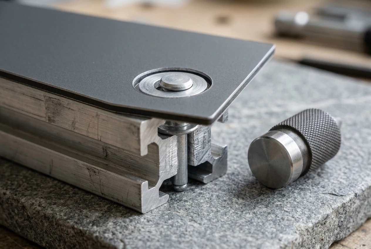
Best practice recommends preparing rainscreen panels with an oversized hole (in relation to the proposed rivet diameter) calculated on anticipated panel and sub-frame expansion, with the rivet accurately fixed in the centre of the panel hole.
For riveted and screwed ALUCOBOND connections, the minimum edge distance is 15 mm, bore holes must be large enough for expected thermal expansion, and linear thermal expansion is 2.4 mm at a 1 m panel length and 100°C temperature difference. For outdoor riveting of ALUCOBOND with an Ø 5 mm aluminium blind rivet and stainless steel mandrel (rivet head Ø 11 or 14 mm), the substructure hole is Ø 5.1 mm and the panel hole is Ø 7.0 mm for Rivet K11 or Ø 8.5 mm for Rivet K14. When the shaft of the rivet fits closely to the edge of the panel hole at maximum thermal movement, the rivet head must cover over 1 mm of the area surrounding the hole. Rivet clamping thickness equals the thickness of the material to be riveted plus an additional value of 2 mm to ensure the closing head is formed, with a minimum shaft length L min. = 14 mm.
When fastening ALUCOBOND with stainless steel fascia screws and EPDM sealing washers, screws must be tightened without exerting pressure on the panel; visible washer deformation or lateral rubber protrusion blocks panel expansion. EJOT drilling screws JT4-FR-2H/6 (4.8 x 22 mm) with a centring sleeve are suitable for ALUCOBOND panel thickness 4 mm and aluminium substructures with a web thickness of 2 mm.
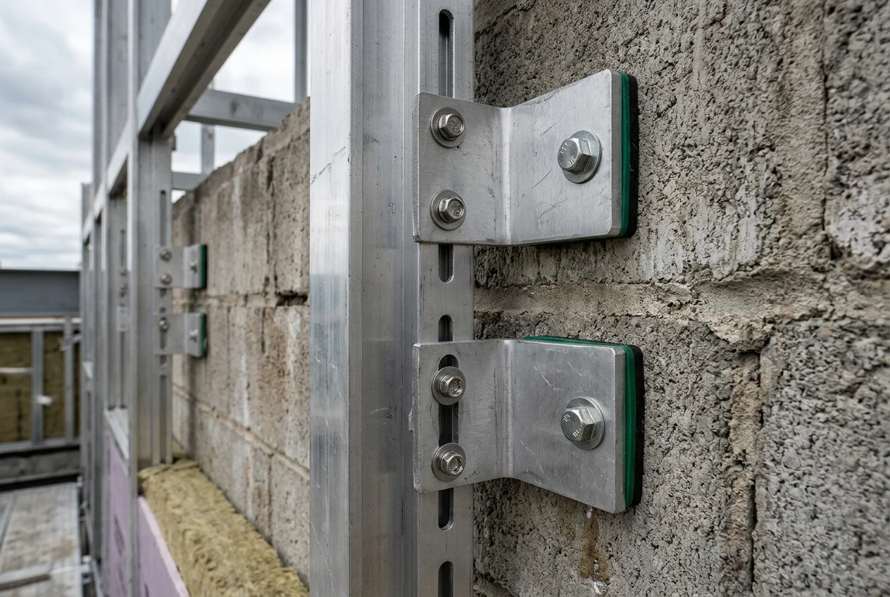
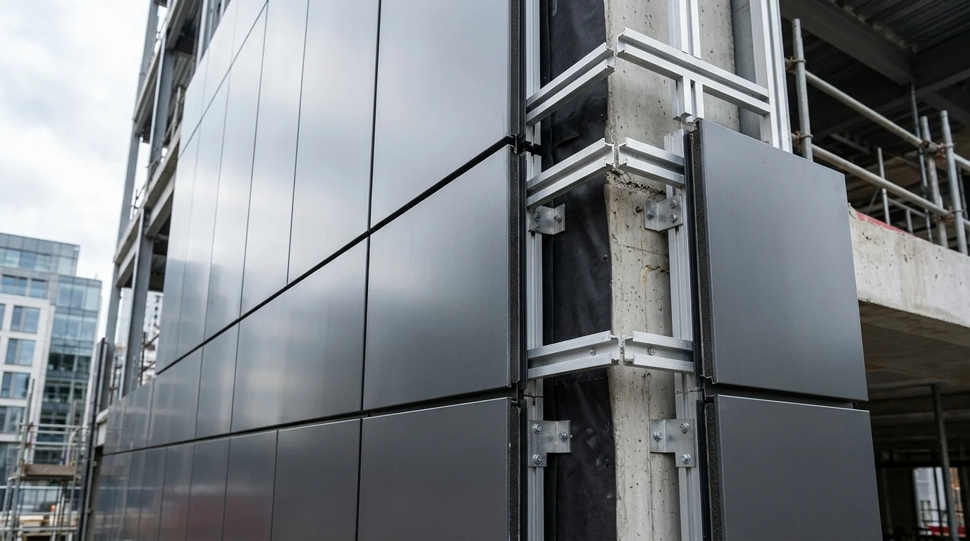
Aluminium rail fixing uses two connection types: a fixed connection secured through a round hole or drilling both sections, and a floating/expansion connection installed into a slotted hole in the first section and drilling and tapping into the second section.
Aluminium rail fixing uses two connection types: a fixed connection secured through a round hole or drilling both sections, and a floating/expansion connection installed into a slotted hole in the first section and drilling and tapping into the second section. Substructure joints must be taken into account when fixing facade elements and must not be skipped—facade elements must not be fixed to both the lower or upper supporting section, and the butt joint of the supporting section must align with the panel joint. Bi-metallic self-drilling fasteners drill and thread-form into a pre-determined steel thickness typically in a range up to 12-14mm; using a fastener designed for 12mm steel in 2.5mm steel creates an oversized hole and minimal thread engagement. In a build-up clamping range example, a 3mm bracket + 12mm cement particle board + 2.5mm steel equates to a build-up thickness of 17.5mm, requiring a fastener with an effective thread length greater than 17.5mm.
Fixed clips, sliding clips, and concealed hem fastening
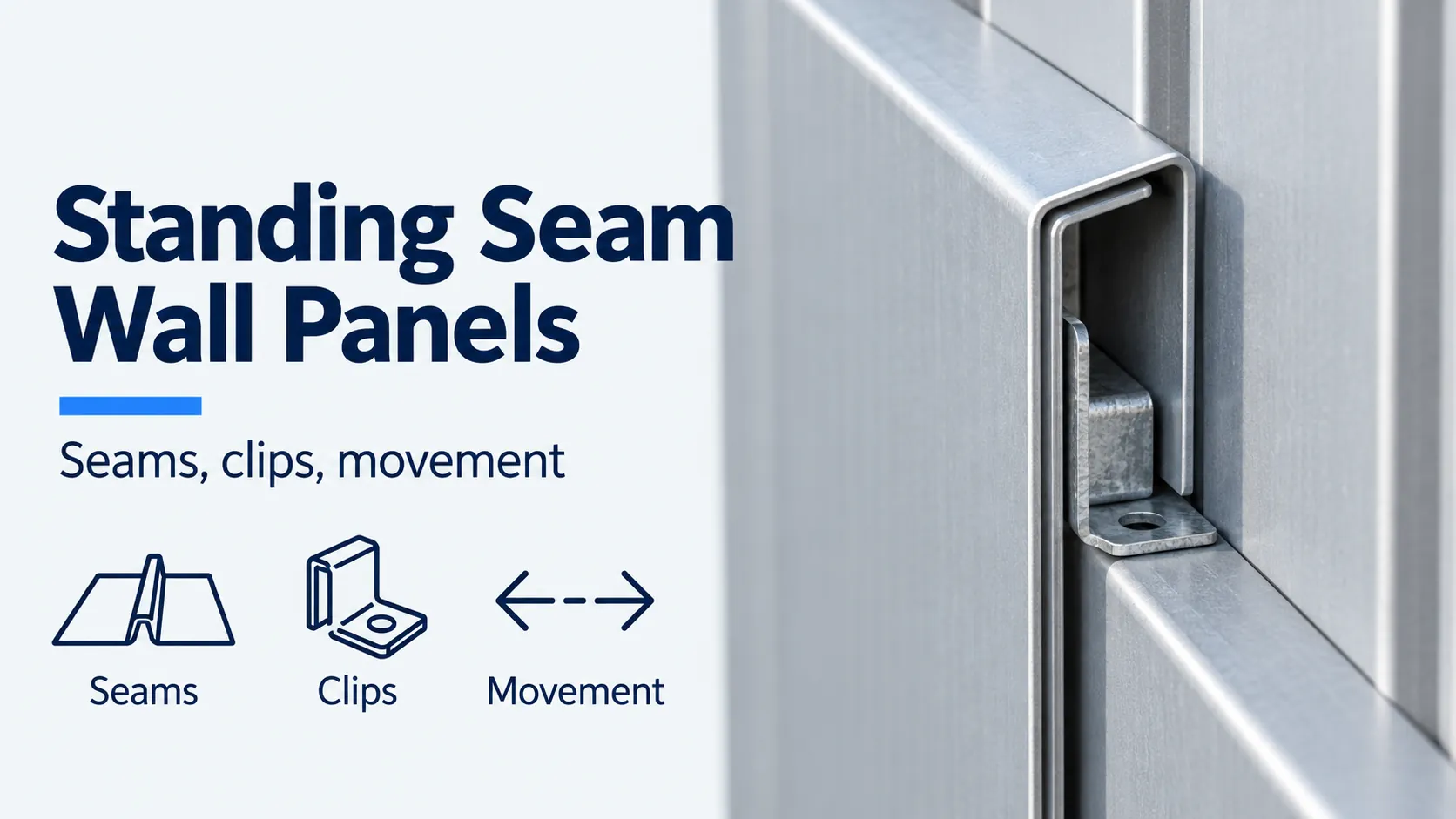
In standing seam wall panel assemblies, the fixed clip acts as the structural restraint while the sliding clip is an engineered movement component—leaving a fastener screw loose is not a substitute for a sliding clip (for example, a 4 m zinc strip undergoes 5.28 mm of free growth over a 60 K change). In PREFALZ facade installations, tray lengths up to 3 meters can be installed with fixing clips only, and panel lengths of up to 12 metres are possible when using PREFA stainless steel preformed sliding clips in accordance with PREFA installation guidelines. For nailed PREFALZ standing seam clips, PREFA stainless steel fixed clips must be installed with 2 stainless steel grooved nails, while PREFA stainless steel sliding and long sliding clips must be installed with 3 stainless steel grooved nails. For screwed PREFALZ standing seam clips, PREFA specifies using 2 countersunk screws per clip for fixed clips, sliding clips, and long sliding clips. PREFA stainless steel fixed, sliding, and long sliding clips are only suitable for even and solid surfaces and only for seam heights of 25 mm.
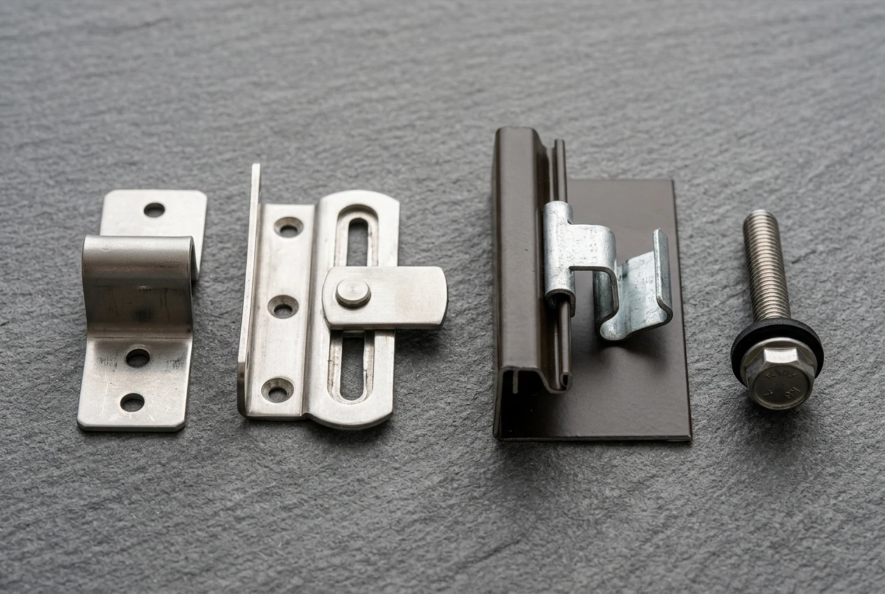
Fixed clips restrain the panel at a designated anchor zone while slotted sliding clips accommodate thermal expansion along the panel length (such as 5.28 mm of free growth on a 4 m zinc strip over a 60 K change).
RHEINZINK Standing Seam Facade System guidelines specify 0.8 mm thickness for face heights 16” to 24”, 0.7 mm thickness for Standard Panel widths from 12” to 16.75”, and limiting panel lengths to 13’-0” for ease of fabrication and installation. Metal Sales states that Contempra panel clip fasteners must not be overtightened and must be brought just to firm contact so the panel remains capable of sliding along its length after the clips are installed. Metal Sales Contempra CN88-1212 concealed fastened clips are G90 material with 2 fastener holes; overdriving the clip can crush the open hem and cause panel distortions, and fasteners should extend 1/2” or more past the inside face of steel and wood support. McElroy Metal Wave concealed-fastener wall panels distinguish between Fixed Wave Panel Fastening and Floating Wave Panel Fastening with the MT-193 Wave Clip. ZT Steel Structure warns against requesting slotted anchor holes or loose fasteners as a substitute for engineered building expansion planning and a thermal interface coordination checklist.
For folded-seam clip mechanics and wall profile options, review standing seam wall panels in our systems hub.
Expansion joint reveal widths, end laps, and framing tolerances
For exposed fastener systems, Sentrigard recommends limiting exposed fastened aluminum panels to 16’ long and steel panels to 40’ or 45’ maximum length, using end laps with butyl sealant for longer runs. Sentrigard states that if the panels must be installed during summer or winter it may be best to pre-drill holes in the panels larger than the screw thread diameter to aid in expansion/contraction of the panels. ASC Building Products specifies a Long Panel End Lap detail (with 6” lap min., 2 rows butyl mastic tape or gunnable sealant, and a 2” offset between 2 #14 wood screws and #10 pancake head screws) for panels 28 ft. or longer so upper and lower panels expand and contract independently.
Ruukki Liberta rainscreen panel fastening instructions specify ±1 mm panel tolerances (A-, B-, and Dh/Dv-dimensions), Dh = 10 horizontal joint dimension, and ±1 mm horizontal sub-frame tolerances for one panel and between support studs. Allowable bending deflection of framing members for cladding rails is limited to Length/200 where member length is less than 3 metres, and Length/300 +5mm for floor-spanning support systems. Rainscreen support system adjustment reduces primary/back wall structure deviations down to tolerances typically within ±3mm per storey height or structural bay, and ±5mm overall length or height of the building.
Metal Sales Contempra Series installation instructions state that wall support variance from in-plane should not exceed 1/4” in 10’, and recommend spacers with a minimum depth of 1/4” at clips and trims to allow water to drain. Anthony Birchler of Zahner notes a 120 inches (roughly 3 meters) outdoor metal length can experience a temperature differential of as much as 100 F (38 C), and states a three-to-one rule to design return leg movement joints on rainscreen plate panel facades to accommodate at least three times the anticipated movement plus the fabrication and erection tolerances. Simpson Gumpertz & Heger (SGH) notes panels may disengage from their attachment clips if there is not enough interlock to accommodate thermal movement, and recommends aluminum stiffeners commonly spaced 610 mm (24 in.) on center.
Published panel length thresholds, clearance hole dimensions, and support alignment values by manufacturer or guide.
| System or guide | Published movement, hole, or alignment specification |
|---|---|
| ALUCOBOND blind rivets | For outdoor riveting of ALUCOBOND with an Ø 5 mm aluminium blind rivet and stainless steel mandrel (rivet head Ø 11 or 14 mm), the substructure hole is Ø 5.1 mm and the panel hole is Ø 7.0 mm for Rivet K11 or Ø 8.5 mm for Rivet K14. |
| EJOT centering screw | EJOT drilling screws JT4-FR-2H/6 (4.8 x 22 mm) with a centring sleeve are suitable for ALUCOBOND panel thickness 4 mm and aluminium substructures with a web thickness of 2 mm. |
| PREFA PREFALZ facade trays | In PREFALZ facade installations, tray lengths up to 3 meters can be installed with fixing clips only, and panel lengths of up to 12 metres are possible when using PREFA stainless steel preformed sliding clips in accordance with PREFA installation guidelines. |
| RHEINZINK facade panels | RHEINZINK Standing Seam Facade System guidelines specify 0.8 mm thickness for face heights 16” to 24”, 0.7 mm thickness for Standard Panel widths from 12” to 16.75”, and limiting panel lengths to 13’-0” for ease of fabrication and installation. |
| Sentrigard exposed fastener sheets | For exposed fastener systems, Sentrigard recommends limiting exposed fastened aluminum panels to 16’ long and steel panels to 40’ or 45’ maximum length, using end laps with butyl sealant for longer runs. |
| ASC Building Products long panel end lap | ASC Building Products specifies a Long Panel End Lap detail (with 6” lap min., 2 rows butyl mastic tape or gunnable sealant, and a 2” offset between 2 #14 wood screws and #10 pancake head screws) for panels 28 ft. or longer so upper and lower panels expand and contract independently. |
| Ruukki Liberta rainscreen cassettes | Ruukki Liberta rainscreen panel fastening instructions specify ±1 mm panel tolerances (A-, B-, and Dh/Dv-dimensions), Dh = 10 horizontal joint dimension, and ±1 mm horizontal sub-frame tolerances for one panel and between support studs. |
| MCRMA support rail alignment | Rainscreen support system adjustment reduces primary/back wall structure deviations down to tolerances typically within ±3mm per storey height or structural bay, and ±5mm overall length or height of the building. |
Frequently asked questions
How do you calculate thermal expansion movement in metal wall panels?
Sentrigard defines change in sheet length (in inches) as ∆L = 12(∆T)(L)(E), where ∆T is temperature change in degrees F, L is total sheet length in feet, and E is the coefficient of linear expansion. Metal Sales gives Δ Length (in inches) = Length (in inches) * Δ Temperature (in °F) * ε, with ε = 0.0000065 / °F for steel and 0.0000128 / °F for aluminum, yielding 0.78" expansion on a 100' long steel panel over a 100°F change (and 1.56" for aluminum). Petersen Aluminum (PAC-CLAD) states that aluminum expands and contracts almost twice as much as steel: for every 100°F temperature swing, a 30-foot aluminum panel could move about 7/16 of an inch, while a similar steel panel might move only about one quarter inch.
Does metal sheet gauge or copper weight change the thermal expansion coefficient?
Deer Park Roofing states that the coefficient of expansion is constant across all metal thicknesses, so 24-gauge galvanized steel has the same coefficient as 26-gauge galvanized steel, and 16-ounce copper has the same coefficient as 20-ounce copper. RHEINZINK architectural titanium zinc has an expansion coefficient of 2.2 mm/m x 100 K in the rolling direction and 1.7 mm/m x 100 K transverse to the rolling direction.
How are oversized rivet holes and axial clearances detailed on aluminum composite panels?
For outdoor riveting of ALUCOBOND with an Ø 5 mm aluminium blind rivet and stainless steel mandrel (rivet head Ø 11 or 14 mm), the substructure hole is Ø 5.1 mm and the panel hole is Ø 7.0 mm for Rivet K11 or Ø 8.5 mm for Rivet K14. When the shaft of the rivet fits closely to the edge of the panel hole at maximum thermal movement, the rivet head must cover over 1 mm of the area surrounding the hole. Rivet clamping thickness equals the thickness of the material to be riveted plus an additional value of 2 mm to ensure the closing head is formed, with a minimum shaft length L min. = 14 mm.
Why do rainscreen panels and support rails need both fixed points and slotted holes?
Aluminium rail fixing uses two connection types: a fixed connection secured through a round hole or drilling both sections, and a floating/expansion connection installed into a slotted hole in the first section and drilling and tapping into the second section. Rainscreen panels require a fixed point to avoid slippage because if all holes in the panel are oversized and the fastener is held off, the panel will slip; fixed point sleeves can also create a fixed point inside an oversized hole. Substructure joints must be taken into account when fixing facade elements and must not be skipped—facade elements must not be fixed to both the lower or upper supporting section, and the butt joint of the supporting section must align with the panel joint.
Can installers leave exposed fasteners or clip screws loose to allow panel movement?
No — the fixed clip provides the structural restraint while the sliding clip is an engineered movement assembly; leaving a screw loose is not a sliding clip. For example, a 4 m zinc strip undergoes 5.28 mm of free thermal growth over a 60 K temperature change. Metal Sales states that Contempra panel clip fasteners must not be overtightened and must be brought just to firm contact so the panel remains capable of sliding along its length after the clips are installed. When fastening ALUCOBOND with stainless steel fascia screws and EPDM sealing washers, screws must be tightened without exerting pressure on the panel; visible washer deformation or lateral rubber protrusion blocks panel expansion. ZT Steel Structure warns against requesting slotted anchor holes or loose fasteners as a substitute for engineered building expansion planning and a thermal interface coordination checklist.
Sources
- Metal Wall Panel Installation — Metal Coverings
- Oil Canning in Metal Panels — Metal Coverings
- Technical Bulletin: Expansion of Long Length Sheets — Sentrigard Metal Roofing Systems
- ALUCOBOND Processing and Technical Data — ALUCOBOND
- Rainscreen Fixings and Fastenings Guidance Document — MCRMA
- Introduction to Rainscreen Support Systems Guidance Document — MCRMA
- PREFALZ Installation Guidelines: Fastening the Panels — PREFA
- PREFALZ Facade Installation: Clip Arrangement — PREFA
- Standing Seam System Technology for Facades — RHEINZINK
- Architectural Titanium Zinc Material Properties — RHEINZINK
- Liberta Rainscreen Panels Fastening Instruction — Ruukki
- Contempra Series Installation Guide — Metal Sales Manufacturing
- Thermal Expansion in Metal Panels — Metal Sales Manufacturing
- Thermal Expansion and Contraction in Metal Roof Systems — Petersen Aluminum
- Light Gauge Installation Guide — ASC Building Products
- Wave Panel Installation Manual — McElroy Metal
- Designing For Thermal Movements in Metal Architecture — Metal Architecture
- Navigating the Challenges of Rainscreen Cladding — Metal Architecture
- Understand Thermal Movement — Deer Park Roofing
- Managing Thermal Expansion in Steel Building Design — ZT Steel Structure