A wrong core substitution or an over-routed fold can turn aluminum composite panels into a costly façade replacement problem. Aluminum composite panels bond two aluminum skins to a core; specify the exact core and attachment system, check the applicable wall-assembly fire evidence, and use the selected manufacturer’s routing and folding instructions. NFPA 285 evaluates exterior-wall fire propagation, while the fabrication detail determines how much material remains beneath a routed groove and how the finished panel accommodates movement at its fixings and joints.
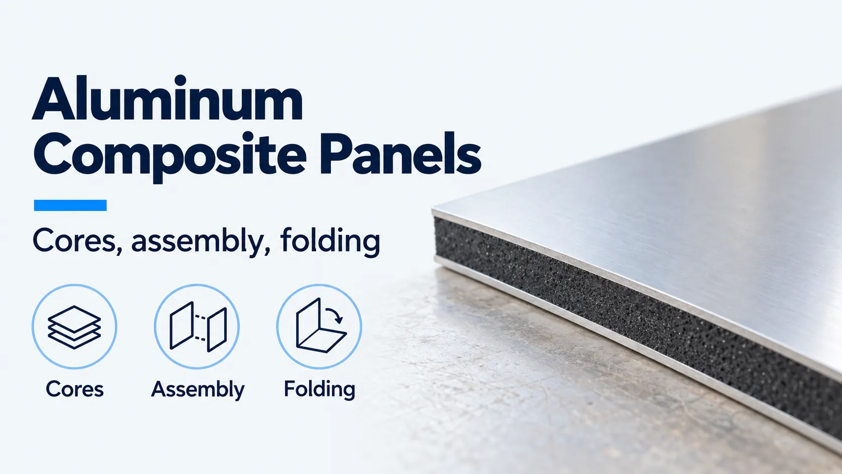
The labels identify the primary specification checks across the panel skin, core, and perimeter edge.
| Input or item | Typical value or source | Why it matters |
|---|---|---|
| Material identity | ACP; also ACM when referring to aluminum composite material | Distinguishes bonded sheet from solid aluminum plate |
| Core | Exact product: polyethylene, mineral-filled thermoplastic or another documented construction | A finish sample does not identify the core |
| Fire evidence | Project-relevant wall-assembly documentation and adopted code review | A material name does not establish an assembly result |
| Fold | Product-specific groove profile and residual layers | Cutting too deeply can damage the retained face |
| Movement | Panel coefficient, temperature change and attachment geometry | Tight fixings can restrain otherwise adequate joints |
Use the metal cladding materials hub for metal selection and aluminum wall panels when comparing composite sheet with solid aluminum forms. The metal wall coverings guide places that material decision alongside system and application.
What is inside an aluminum composite panel?
An ACP has two aluminum faces bonded to a core; the core must be identified by its actual product designation. In the named examples, ALPOLIC/PE uses thermoplastic polyethylene, while ALPOLIC/fr uses mineral-filled thermoplastic. Mineral filler changes the formulation; the word “mineral” does not establish that the whole panel is polymer-free.
Review the core before selecting a finish. Two sheets can share a color and external appearance while differing in core formulation, fabrication instructions and supporting fire documentation. Keep the ordered product designation traceable through fabrication and installation.
| Construction | What to establish | Dominant Failure Mode & Prevention |
|---|---|---|
| Polyethylene-core ACP | Named PE product and its documented application | Substituting a visually similar panel with different core → check product identity against the approved project documents |
| Mineral-filled thermoplastic ACP | Exact formulation/product and assembly evidence | Reading “FR” as a complete wall approval → review the actual assembly record and permitted configuration |
| Solid aluminum panel | Alloy, thickness, stiffening and fixing design | Copying a composite panel’s fabrication or support assumptions → use solid-panel engineering and forming details |
| Insulated metal panel | Factory sandwich, insulation and joint system | Treating a thin ACP skin as the insulation layer → select an enclosure build-up with documented thermal and seal performance |
These rows compare constructions and review risks. They do not rank products or assign a fire classification to an unspecified panel.
What does NFPA 285 measure?
NFPA 285 evaluates fire propagation characteristics of exterior wall assemblies containing combustible components. The NFPA exterior-wall overview identifies that assembly-level scope; it does not establish a result for an unnamed ACP.
For project review, collect the exact cladding/core designation and the supporting wall-assembly record. Compare the proposed backing, insulation, weather-resistive layers, cavity, attachment and opening details with the documented configuration. Record proposed substitutions so the design team can determine what evidence addresses them.
An aluminum face, an “FR” label or a general brochure statement is insufficient to identify the wall tested. This guide assigns no NFPA 285 result to any product or project and supplies no universal building-height trigger. Applicability depends on the adopted code and proposed wall; the metal wall panel fire performance guide explains the broader specification questions.
How do routing and folding create a returned panel?
Route-and-return fabrication removes material from the rear along a fold line while preserving the visible aluminum face and a controlled core residue. The thinned section can then fold into a return; the groove does not cut through the exposed face.
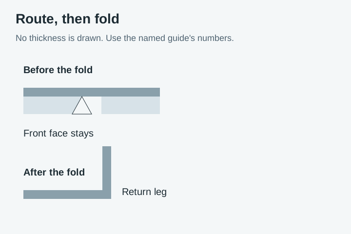
No thickness is drawn. The residual-core numbers stay in the cited fabrication guide.
The ALUCOBOND processing guide, printed pp.16–19, describes rear V-shaped or rectangular grooves. Its disk-cutter setup specifies 0.3 mm residual core for a V-groove or 1 mm for a rectangular groove, in addition to the 0.5 mm aluminum face shown in those details. These dimensions belong to the described nominal panel and tooling, accessed October 19, 2026.
Set tooling from the selected product’s guide and verify the remaining section on a trial piece before routing production sheets. An overall sheet thickness alone does not define the depth setting: the face thickness, required residue and groove geometry also matter. The return, corner closure and attachment then need their own fabrication details.
How is thermal movement calculated?
Calculate free growth using the selected panel coefficient and the distance that must move relative to its restraint.
ΔL = α × L × ΔT
ΔL is growth in mm, α is in mm/(m·K), L is length in m and ΔT is temperature change in K. The same ALUCOBOND guide, printed p.24, gives 2.4 mm/m per 100 K, equivalent to α = 0.024 mm/(m·K), for that material.
Worked example — assumed inputs: a 2 m panel experiencing a uniform 50 K rise grows by ΔL = 0.024 × 2 × 50 = 2.40 mm.
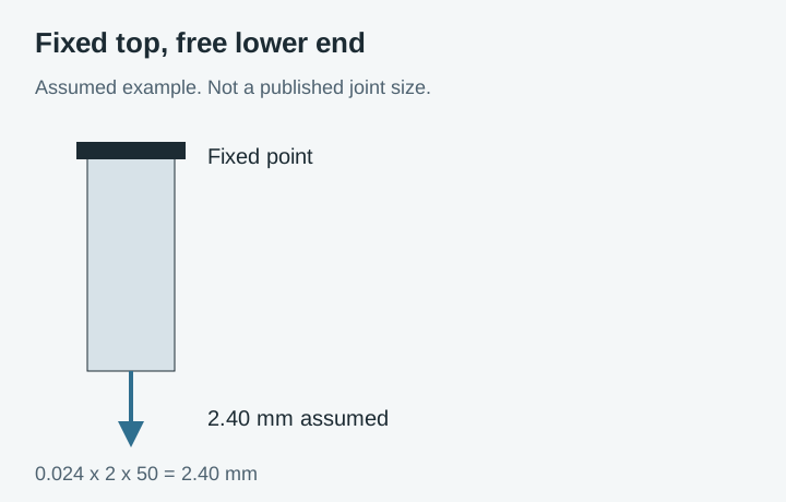
The 2.40 mm arrow is the assumed example above, not a published joint size.
For an assumed fixed point at the top and free movement below, the lower end must accommodate that full calculated growth before tolerances. A different restraint arrangement changes its distribution. The guide also calls for fixings that allow movement; verify usable clearance at the connection as well as at the visible joint.
Rules of Thumb for fabrication and movement
If a trial V-groove leaves less than the named guide’s 0.3 mm core target, stop and verify the setup. That target applies to the cited ALUCOBOND disk-cutter detail; use the correct instruction for another panel or process.
If available directional clearance is less than calculated directional growth, the movement detail is insufficient. In the assumed one-end-fixed example, clearance below 2.40 mm cannot accommodate the stated heating movement even before tolerances. Check cooling from installation temperature separately.
If usable movement at a fixing is zero while thermal demand is positive, an open panel joint cannot solve that restraint. Resolve the connection geometry before fabrication. For a folded-sheet alternative, standing seam wall panels use a different seam and clip arrangement; their attachment details are not interchangeable with an ACP tray.
What belongs in the total cost of ownership?
Include the complete fabricated façade and its maintenance access, rather than comparing raw sheet quantities alone.
| TCO component | What the project should count |
|---|---|
| Material and yield | Exact core/finish, sheet layout, directional finishes, routed offcuts and spare-panel provision |
| Fabrication | Programming, trial pieces, tool wear, routing, folds, corner closure and inspection |
| Supporting system | Rails, brackets, fixings, insulation interfaces and documented movement provisions |
| Approval and coordination | Assembly-document review, substitution review and project-required verification |
| Installation and rework | Access, handling, alignment and replacement of damaged folds or incorrectly identified sheets |
| Service life | Cleaning access, joint inspections, applicable seal maintenance and panel-removal sequence |
The relevant quantities and rates depend on the project. This ledger does not assign prices, predict a service life or claim a savings percentage. Coordinate the fabricated panels with the metal wall panel installation guide before closing the backing and interfaces.
What should the selection record contain?
Keep material identity, fire evidence and fabrication instructions together so a later substitution can be checked against the original decision.
- Record manufacturer, exact core/product designation, thickness and finish direction.
- Identify the project-relevant assembly documentation and the proposed configuration it addresses.
- Attach the selected groove, retained-layer, fold and corner details.
- Mark fixed and moving connections, assumed panel temperatures and directional allowances.
- Identify inspection access and the sequence for replacing an individual panel.
Return to the materials hub if the choice is still between a composite and solid metal face; use the insulated-panel guide when the required function is a factory enclosure rather than an outer architectural skin.
Method and sources
This guide uses the linked ALPOLIC core descriptions, ALUCOBOND fabrication instructions and NFPA scope overview accessed October 19, 2026. Manufacturer values remain specific to the cited products and processes. The calculation uses declared assumptions; the review and cost tables are editorial checklists, with no unnamed product approval or test result asserted.
Last updated: October 19, 2026.
Sources
- ALPOLIC/PE: Polyethylene-core aluminum composite panel — ALPOLIC Accessed October 19, 2026.
- ALPOLIC/fr: Mineral-filled thermoplastic core — ALPOLIC Accessed October 19, 2026.
- ALUCOBOND Processing and Technical Data, Edition 3 — 3A Composites Accessed October 19, 2026.
- Understanding and managing the fire hazards of exterior walls containing combustible components — National Fire Protection Association Accessed October 19, 2026.