Direct answer
Choose metal wall panel sizes from the installed cover width or finished module first, then check stock, blank and face dimensions, thickness and support for the exact system.
Choosing a panel by its sheet size can leave narrow cuts beside windows and offcuts that cannot be reused.
| Dimension | Quick check |
|---|---|
| Stock sheet | Available raw format for the exact product and finish |
| Fabrication blank | Includes the fabricator’s returns and processing allowances |
| Cover width / installed module | Repeat used to coordinate the elevation and joints |
| Finished face | Visible surface; confirm where its adjoining reveal is counted |
If you have not yet chosen between a formed panel, cassette and composite assembly, start with the metal wall coverings overview to identify the system family.
This guide develops the dimension choices within metal cladding design and specification. It focuses on panel layout and what belongs in a size schedule. Manufacturer examples show how to read dimensions, rather than establish a universal range of acceptable wall panels.
Read the dimensions before comparing panels
Start by asking what the number measures. A supplier may describe a raw sheet by length and width, a roll-formed product by its coverage, or a cassette by its finished face. Those numbers belong to different stages of making a wall. Putting them in one spreadsheet column labelled “panel size” hides information you need to order correctly.
| Dimension | What it describes | What to verify before using it |
|---|---|---|
| Stock sheet size | Material available before cutting or forming | Exact product, finish, core where relevant, and usable stock dimensions |
| Fabrication blank | Piece needed to make the finished component | Returns, folds, edge processing and the fabricator’s allowances |
| Overall panel width | Physical width of the formed panel | Whether it includes engagement or overlap that will be concealed |
| Cover width or installed module | Repeating increment on the elevation | The manufacturer’s definition and how joints are counted |
| Finished face | Visible panel surface | Whether the adjoining reveal is outside this dimension |
| Panel length | Length of the ordered piece | End details, manufacturing limits, delivery and handling arrangements |
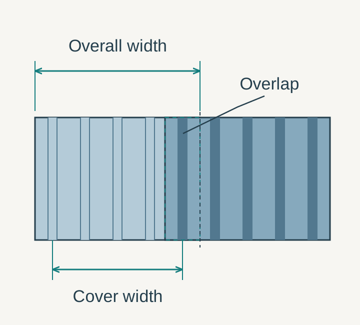
For repeating single-skin metal panels, the product drawing should identify the installed increment. For metal cassette panels, establish whether the schedule describes the visible face, the joint-to-joint module or the fabrication blank. A joint cannot be counted twice simply because one drawing labels the face and another labels the module.
Take a simple arithmetic example: a hypothetical 240-inch-wide rectangular area divided by a confirmed 16-inch installed increment contains 15 increments. That is a layout check, not an order for 15 panels. Starting and ending conditions, openings, corner details and cutting decisions still have to be resolved. If the quoted 16 inches is only a nominal width, even that first calculation needs confirmation.
Takeaway: label each dimension by what it measures before comparing sizes or calculating quantities.
Check manufacturer examples without making them universal
The following examples were checked against published manufacturer pages in October 2026. They deliberately represent different dimension conventions. They are not interchangeable products, a complete market survey or confirmation of current stock at a particular branch.
| Published example | Dimensions or thickness stated by the manufacturer | What the example demonstrates |
|---|---|---|
| McElroy Metal Wave | 16-inch cover width; 24-gauge Galvalume; fixed configuration up to 40 feet and floating configuration up to 50 feet in factory panel length | Product length depends on the installation configuration; length is not an unsupported-span rating |
| PAC-CLAD Precision Series Highline | 12- or 16-inch nominal widths; 1-3/8-inch profile depth | Nominal width and profile depth are separate dimensions; obtain the exact profile drawing |
| ALPOLIC BNT Bone White FR stock example | 4 mm × 50 inches × 196 inches and 4 mm × 62 inches × 196 inches in the manufacturer’s stock explanation | Core, finish and dimensions form one stock combination; the 4 mm describes the composite, not solid aluminum thickness |
Sources: McElroy Wave, PAC-CLAD Highline and ALPOLIC’s stock explanation.
The ALPOLIC example is particularly useful when a quotation says a color is “standard.” Its manufacturer explains that stock status belongs to a combination of attributes. Do not assume every width, thickness or core is available because the finish name appears on a standard-color list. Request the exact combination and the date of the availability confirmation.
Likewise, do not turn a manufacturer’s maximum production length into the preferred length for every elevation. A long uninterrupted piece still has to arrive, be handled and meet the specified attachment and movement arrangement. The Wave page distinguishes fixed and floating configurations; that distinction should survive when its dimensions are copied into a schedule.
Common mistake: copying the largest catalog dimension into the drawings while leaving the product configuration unspecified. Ask which configuration, material and installation detail support that dimension.
For composite terminology, see what MCM cladding means. It prevents a thickness comparison between a solid sheet and a complete sandwich panel from appearing more precise than it is.
Takeaway: keep every published dimension attached to its product, material and configuration.
Coordinate the panel grid with openings and corners
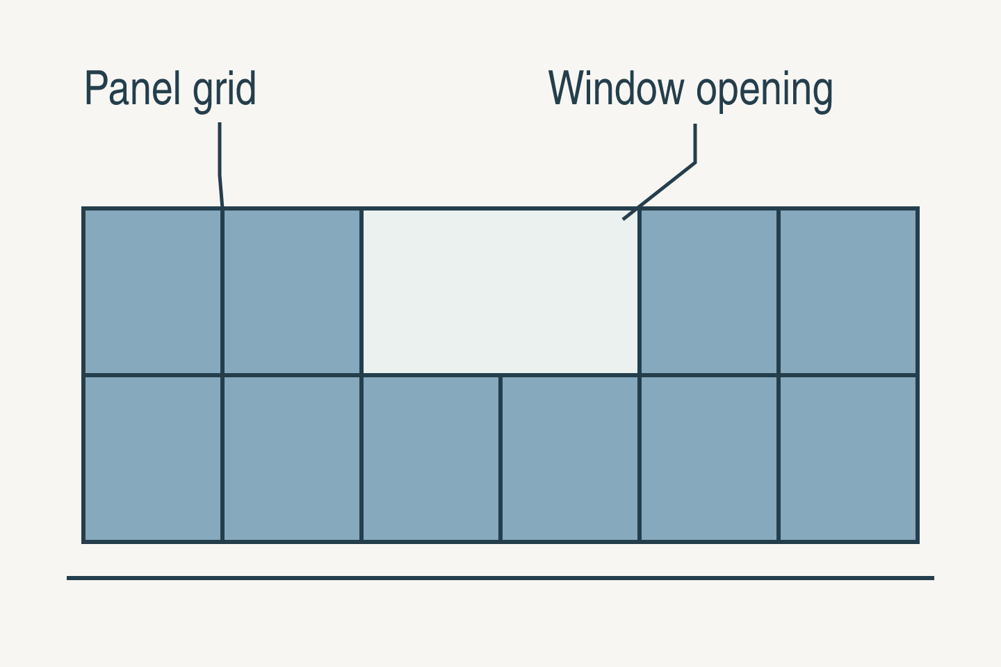
A regular module can look straightforward on an uninterrupted wall and become awkward at the first window. The useful drawing is the entire elevation: openings, corners, base, top edge and changes of plane shown against the panel joints. A cropped sample of three panels cannot reveal the pieces that will be needed at the ends.
Begin with the dimensions that are already constrained. These may include existing window positions, structural lines, required access openings or a fixed corner condition. Mark which dimensions can still move and who can approve a change. This avoids treating a window location as adjustable after another trade has already ordered it.
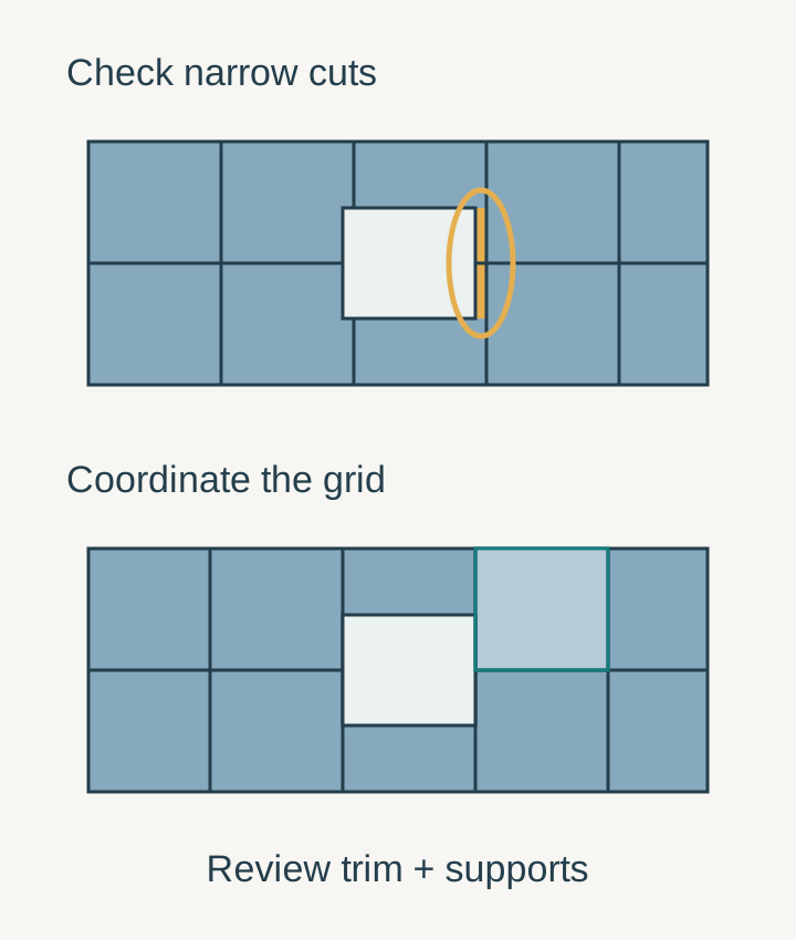
Review the drawing in this order:
- Set a reference line. State where the repeating module starts. A contractor should not have to infer whether the pattern is centred, aligned to a corner or aligned to an opening.
- Carry the grid across the full elevation. Keep the same reference when the wall passes above and below windows. Mark any deliberate change in module.
- Inspect the remaining pieces. Flag narrow jamb strips, short pieces at the top or base, and cuts close to formed edges. Ask the fabricator which can be produced and the designer how they will be supported.
- Resolve the corners and trims. Show the dimensions those components consume. An attractive front elevation is incomplete if its last panel cannot meet the corner detail.
- Assign panel marks. Give non-repeating pieces their own identifiers. Link those identifiers to the cut list and drawing revision.
There is no universal minimum acceptable strip width in this guide. A cut that works for one formed profile may remove a necessary fixing or engagement feature from another. The issue is not only whether a narrow piece looks balanced; it must remain a component the specified system can accommodate.
For exterior metal wall panels, coordinate this elevation exercise with water-management and opening details. If the system is a metal rainscreen, the visible grid also needs to be reconciled with the support arrangement behind it. Neither relationship can be checked from the panel face alone.
Takeaway: settle the reference line, opening interfaces and edge pieces before freezing the module.
Choose thickness together with profile and support
Thickness matters, but the label on the quotation must be clear. A gauge designation on a steel sheet, a depth across a formed rib and a thickness across a composite panel do not measure the same thing. Record the material and thickness basis rather than treating every number as a comparable measure of stiffness.
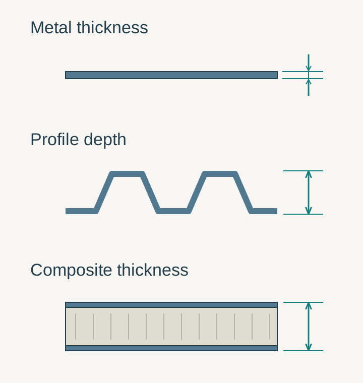
The Metal Construction Association’s oil-canning bulletin explains that visible waviness generally becomes more pronounced as the flat portion widens or the metal becomes thinner. It also describes thicker metal, profile ribs and lower-gloss finishes as ways to reduce likelihood or visual prominence. None amounts to a promise of a perfectly flat finished wall.
Keep that appearance review separate from structural adequacy. A visual sample does not establish an allowable support spacing, and a thickness alone does not establish the load capacity of a wall system. The proposed profile, material, attachment and support arrangement need the project-specific verification assigned to the responsible designer and manufacturer.
Ask for three distinct responses when a thickness change is proposed:
| Question | Useful response | Incomplete response |
|---|---|---|
| What exactly changes? | Revised material and thickness designation for the named product | “A heavier panel” without an updated specification |
| What happens to fabrication? | Confirmation of the available profile, folds, connections and finish | Assuming the old fabrication details remain valid |
| What appearance is being evaluated? | A relevant sample or mockup with agreed viewing conditions | A small color chip offered as proof of full-panel flatness |
The aluminum versus steel wall panel comparison covers the material decision. The separate oil-canning guide examines waviness in more detail; this page does not prescribe field remedies or an acceptance tolerance. Review metal panel finishes when judging reflections, rather than changing thickness while ignoring the specified appearance.
Takeaway: specify what thickness means, then review appearance and structural requirements as separate checks on the same system.
Build a cut list instead of subtracting openings blindly
“Metal wall panels 4×8” often describes a nominal sheet format: four feet by eight feet, or 48 by 96 inches. That callout does not say whether the material is a plain sheet, a fabricated cassette or a tested wall assembly. Nor does it promise a 48-by-96-inch visible face after processing.
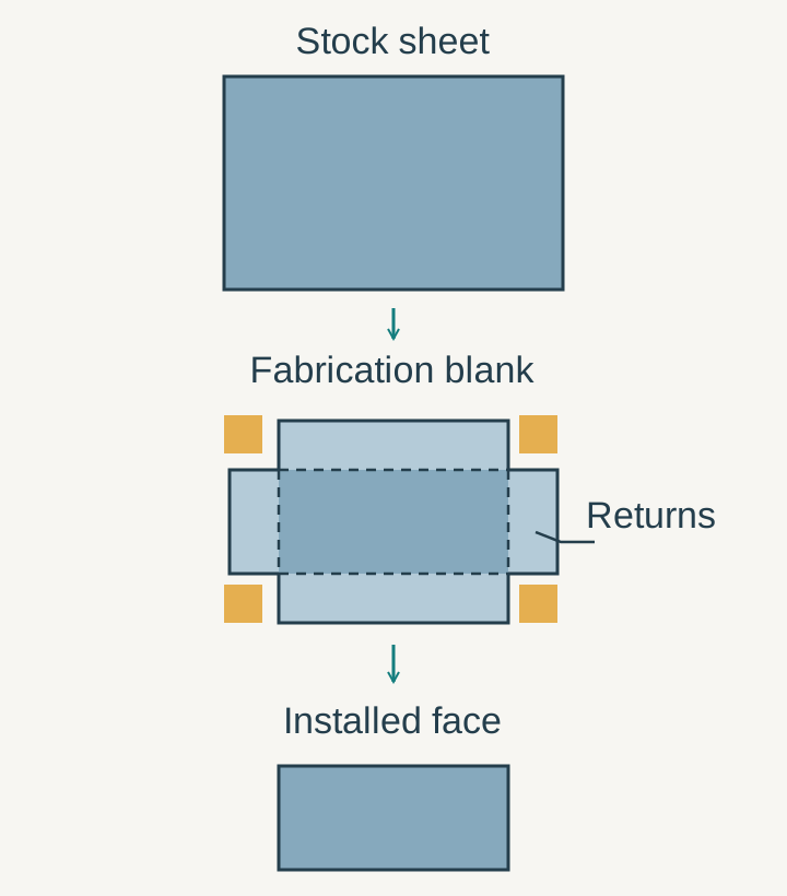
Consider an intentionally simplified nesting example. Suppose a fabricator has already specified a 26-by-50-inch rectangular blank for a particular component. On a nominal 48-by-96-inch sheet, two of those blanks do not fit side by side: 26 + 26 is 52 inches. They do not fit end to end either: 50 + 50 is 100 inches. Rotating a blank puts its 50-inch side across a 48-inch sheet. A simple rectangular layout therefore yields one complete blank before edge trimming or cutting allowances are considered.
The lesson is the check, not those dimensions. They are invented arithmetic inputs, not a recommended panel size, return allowance or production yield for a manufacturer. A fabricator may propose different stock, a changed face size or a different component strategy. Ask to see the resulting layout rather than assuming a smaller visible face automatically produces less waste.
Openings create a related problem. Subtracting window area gives net wall area; it does not identify reusable pieces. A window cutout may have the wrong orientation, damaged or unfinished edges, or dimensions that do not correspond to the next location. Record proposed reuse by panel mark so it can be reviewed rather than treated as an automatic saving.
A working cut list should contain:
- Panel mark and elevation location.
- Product and profile, material, thickness and finish reference.
- Ordered length and the dimension convention used for width.
- Required blank dimensions where the component is fabricated from sheet.
- Quantity, orientation and the relevant drawing revision.
- Factory cuts, planned field cuts and any proposed reuse location.
- Associated trim or closure references and unresolved dimensions.
For corrugated metal wall panels, profile orientation and engagement make a scrap different from a plain rectangular sheet. For metal composite material panels, the fabrication method and finished edges need to remain attached to the cut-list entry. Neither should be reduced to an area-only ordering calculation.
Common mistake: applying a standard waste percentage before checking the actual cuts. Use the layout to identify unusable material and separately record allowances agreed for handling, replacement and installation.
Takeaway: calculate quantities from identifiable pieces and fabrication constraints, not net area alone.
Approve a usable size and thickness schedule
A good schedule lets another person trace an ordered piece back to the wall drawing. It should also make changes visible. If the architect changes a reveal, the fabricator changes a blank or the supplier offers a different stock size, the team needs to know which earlier quantity or approval is affected.
Use one revision-controlled schedule with a short decision record beside it:
| Record | Minimum useful content |
|---|---|
| Dimension basis | Whether each number is stock size, blank, face, overall width or installed module |
| Product identity | Manufacturer, product/profile and applicable configuration |
| Material designation | Metal or composite construction and the specified thickness basis |
| Drawing reference | Elevation, panel mark, joint layout and revision |
| Interface status | Openings, corners, base and top conditions resolved or explicitly outstanding |
| Fabrication confirmation | Blank requirements, feasible cuts and agreed component limitations |
| Appearance review | Sample/mockup reference and what was actually accepted |
| Release status | Who approved the revision and which quantities it authorizes |
Copyable size/thickness record — copy this blank block into the schedule and keep its revision with the drawings:
Product / profile / source document and revision:
Stock size / blank dimensions / installed module / face size:
Material / thickness basis / finish / core if applicable:
Elevation / panel mark / drawing revision:
Opening / corner / base / top interface status:
Fabrication confirmation / cuts / outstanding limits:
Sample or mockup reference / accepted appearance:
Release reviewer / date / quantities authorized:
Before release, pick one ordinary panel, one opening panel and one corner or end condition. Follow each from the elevation to its schedule entry and applicable detail. If the chain breaks at a vague “typical” note, identify the missing decision while the order can still change.
The metal wall panel installation guide is the next reading step once the product and layout are selected. Keep the distinction clear: a size schedule identifies components; installation documentation tells the installer how the selected components are assembled. This site provides editorial guidance, not project approval or a supply quotation.
Takeaway: release a traceable product-and-layout schedule, with unresolved interfaces identified before ordering.
Scope and sources
This guide compares published dimension conventions and offers an editorial workflow for reviewing a panel layout. The hypothetical nesting example is arithmetic, not a fabrication design. No load tests, structural calculations, guaranteed waste savings, supplier inventory checks or site measurements were performed.
Manufacturer values above apply only to the named examples and the documented configurations. Confirm the current product data and project requirements before ordering. Required capacity, supports, fastening, thermal movement, fire performance and opening details remain matters for the selected system and the responsible project team.
The FAQ draws on public questions about mixed panel widths and custom trim, 4×8 sheets for an interior display wall, checking a delivered gauge and ordering and cutting panels around openings. Questions were adapted to the guide; community replies are not technical proof. Published manufacturer pages and the MCA bulletin provide the cited factual evidence.
Frequently asked questions
Can I mix different panel widths on one elevation?
Some product families permit mixed profiles or widths, but a shared brand name is not enough. Confirm joint engagement, support details, finish availability and transition pieces for the exact combination. Draw the mixed pattern through windows and corners before releasing the schedule.
Will custom window trim match the factory panels?
Do not assume it will. Identify the trim supplier, base metal, coating and finish reference, then review the proposed match. A panel dimension is incomplete until the trim face, return and joint it meets have also been coordinated.
Is a 4-by-8 steel sheet suitable for a magnetic display wall?
Sheet size alone does not establish suitability. This is an interior attachment and finish problem as well as a dimension choice. Confirm the sheet material, backing, edges, attachment and intended coating with the supplier and installer; exterior cladding data does not validate that assembly.
Can a measurement over the paint confirm the steel gauge?
It measures what the instrument spans, which may include coatings. Resolve a disputed delivery against the ordered material, specified thickness basis and applicable tolerance, using the supplier's documentation and an agreed measurement method. Do not identify the substrate solely from a generic online conversion chart.
Should I order full-height sheets or separate lengths around windows?
Draw two options for the same opening: full-height pieces with planned cutouts, and separate pieces above and below the window. In the second option, mark every additional panel end and its proposed trim or joint detail. Ask the system supplier and designer to confirm those interfaces before comparing material quantities. A shorter order is not a usable alternative if its extra joints have not been resolved.
Should I use snips or a nibbler for the cuts?
Use the cutting method permitted for the selected panel and coating, rather than a tool recommendation detached from the product. The cut schedule should identify factory and field cuts; the installation instructions determine the approved tools, edge treatment and cleanup.
Sources
- Wave concealed-fastener wall panel: dimensions and installation configurations — McElroy Metal Accessed October 7, 2026.
- Precision Series Highline Wall Panel Systems — Petersen / PAC-CLAD Accessed October 7, 2026.
- What Does Standard Stock and Custom Production Mean? — ALPOLIC Accessed October 7, 2026.
- Oil Canning in Metal Roof and Metal Wall Systems — Metal Construction Association Accessed October 7, 2026.